您好,登录后才能下订单哦!
图像识别DM8127开发攻略——UBOOT的移植说明根据前几篇文章的介绍,想必大家对DM8127软件架构有了全局的认识,下面我们从开发的角度进行裁剪移植最基本的BOOT软件包,嵌入式开发人员拿到一个新的板子,就是要如何让板子能跑得起自己编译和移植的程序,这才有价值,否则直接拿别人的BIN文件直接烧写到板子上没啥意思。
一、DM8127 UBOOT编译说明
DM8127 的UBOOT的版本是u-boot-2010.06, UBOOT代码 和 以前的DM6446-DM368-DM3730平台稍微不同,以前的DM6446-DM368分离UBL和UBOOT两个软件包,DM3730 分离出XLOADR和UBOOT两个软件包,而现在的DM8127是一个UBOOT软件包,里面包含了UBOOTMIN和UBOOT,通过宏来编译得到不同的BIN文件,这里有3个大的宏来区分不同的编译模式。编译UBOOTMIN 和 UBOOT命令和脚本见《图像识别DM8127开发攻略——RDK软件架构浅析及编译》提到的总Makefile和U-BOOT文件夹对应的u-boot\Makefile文件第3320行开始看 ti8148_ipnc_config,同时也要结合看include/configs/ti8148_ipnc.h。
A、#define CONFIG_TI814X_MIN_CONFIG
编译得到UBOOTMIN(u-boot.min.nand 或者 MLO);
对应RDK总的Makefile编译脚本:
ubootmin:
$(MAKE) ubootclean
$(MAKE) ubootbuild MAKE_TARGET=$(PLATFORMCFG)$(SYSTEM_CFG)min$(BINARY_MODE)
$(MAKE) ubootbuild MAKE_TARGET=u-boot.ti
ifeq ($(BINARY_MODE),sd)
cp $(UBOOTDIR)/u-boot.min.$(BINARY_MODE) $(TFTP_HOME)/MLO
cp $(UBOOTDIR)/u-boot.min.$(BINARY_MODE) $(UBOOTDIR)/MLO
else
cp -f $(UBOOTDIR)/u-boot.min.$(BINARY_MODE) $(TFTP_HOME)/u-boot.min.$(BINARY_MODE)
cp -f $(UBOOTDIR)/u-boot.min.$(BINARY_MODE) $(UBOOTDIR)/u-boot.min.$(BINARY_MODE).bk
cp -f $(UBOOTDIR)/u-boot.min.$(BINARY_MODE) /tftpboot/dm8127_min.bin
endif
我们的build_1_uboot-min-nand.sh就是调用上面的脚本执行else这种模式,得到u-boot.min.nand(dm8127_min.bin),这个是针对nand FLASH的情况,是要烧写到板子NAND FLASH上面的。
而我们的build_1_uboot-min-sd.sh也是调用上面的脚本执行ifeq ($(BINARY_MODE),sd),得到MLO,工厂生产,软件调试,最需要这个文件,因为刚做出来的板子NAND 是没有程序的,需要把这个MLO文件和后面编译总的U-BOOT得到的u-boot.bin一起COPY到SD卡(TF卡)。
B、#define CONFIG_TI814X_OPTI_CONFIG
编译得到u-boot.opti.nand这个也是类似UBOOTMIN的宏编译,只不过编译得到的BIN文件是通过串口下载到板子上启动。
对应RDK总的Makefile编译脚本:
ubootopti:
$(MAKE) ubootclean
$(MAKE) ubootbuild MAKE_TARGET=$(PLATFORM_CFG)_ipnc_opti_nand
$(MAKE) ubootbuild MAKE_TARGET=u-boot.ti
cp $(UBOOTDIR)/u-boot.opti.nand $(TFTP_HOME)/u-boot.opti.nand
我们的build_1_uboot-min-opt.sh就是调用到这个脚本执行,得到u-boot.opti.nand,这个是通过PC端的串口软件下载到板子上面去,有些产品设计的时候,由于特殊原因没有SD卡,那么可以使用这种模式去软件调试新生产出来的板子。编译这种模式要注意修改u-boot/Include/configs/ti8148_ipnc.h这个文件,把很多没用的功能屏蔽掉,比如:
#undef CONFIG_CMD_BDI
#undef CONFIG_GZIP
#undef CONFIG_ZLIB
#undef CONFIG_CMD_LOADB
#undef CONFIG_CMD_LOADS
#undef CONFIG_CMD_NFS
#undef CONFIG_CMD_SETGETDCR
#undef CONFIG_CMD_XIMG
#undef CONFIG_CMD_MISC
#undef CONFIG_CMD_ITEST
#undef CONFIG_CMD_FPGA
#undef CONFIG_CMD_EDITENV
#undef CONFIG_BOOTM_NETBSD
#undef CONFIG_BOOTM_RTEMS
#undef CONFIG_CMD_MISC
#undef CONFIG_CMD_IMI
#undef CONFIG_CMD_ITEST
#undef CONFIG_CMD_SOURCE
#undef CONFIG_CMD_IMLS
#undef CONFIG_CMD_ECHO
使用#undef裁剪u-boot的功能,保留网络功能和NAND功能,如果不裁剪,得到的u-boot.opti.nand过大,是不能在DM8127片内的RAM运行的,u-boot.opti.nand和上面提到的MLO都是在DM8127片内的RAM运行,因为外存DDR3都还没初始化!
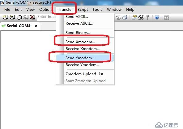
那么软件调试新生产出来的板子时,给板子选定串口BOOT模式(NAND没程序就是自动默认其他BOOT模式),上电,按下图使用串口工具比如SecureCRT,选择编译得到的u-boot.opti.nand,如果串口稳定,一般下载100%正常,回车进入熟悉的u-boot命令行模式。
上图有时使用X modem 传输文件不成功,可以再使用Ymodem模式,波特率使用115200。
C、如果CONFIG_TI814X_MIN_CONFIG和CONFIG_TI814X_OPTI_CONFIG都没有选上,那么就是编译正常的UBOOT,得到u-boot.bin(dm8127_uboot.bin)
对应RDK总的Makefile编译脚本:
ubootbin:
$(MAKE) ubootclean
$(MAKE) ubootbuild MAKE_TARGET=$(PLATFORMCFG)$(SYSTEM_CFG)config$(BINARY_MODE)
$(MAKE) ubootbuild MAKE_TARGET=u-boot.ti
cp -f $(UBOOTDIR)/u-boot.bin $(TFTP_HOME)/u-boot.bin
cp -f $(UBOOTDIR)/u-boot.bin $(UBOOTDIR)/dm8127_uboot.bin.bk
cp -f $(UBOOTDIR)/u-boot.bin /tftpboot/dm8127_uboot.bin
我们的build_2_uboot-all.sh就是调用上面的脚本,第一次编译正常的UBOOT必须使用ubootclean,还有我们的build_2_uboot-tmp.sh是上面的脚本把$(MAKE) ubootclean去掉,在第一次编译build_2_uboot-all.sh后,后面修改源码某个文件,我们不需要每次都调用ubootclean,再重新对所有的文件编译,太浪费时间。
提示:上面3种大的宏编译模式,一定要结合RDK总Makefile和U-BOOT文件夹对应的u-boot\Makefile文件第3320行开始的内容来理解。
二、UBOOT的裁剪和移植
1、 修改u-boot\Makefile
以前写过的其他DAVINCI平台开发攻略都说过,第一步就是删除不相关的文件,这样才好理解这个DM8127平台有哪些相关的文件和文件夹,哪些是不相关的,一目了然。
SUBDIRS = tools \
#examples/standalone \ (屏蔽,不要)
#examples/api (屏蔽,不要)
…….
#LIBS += api/libapi.a (屏蔽)
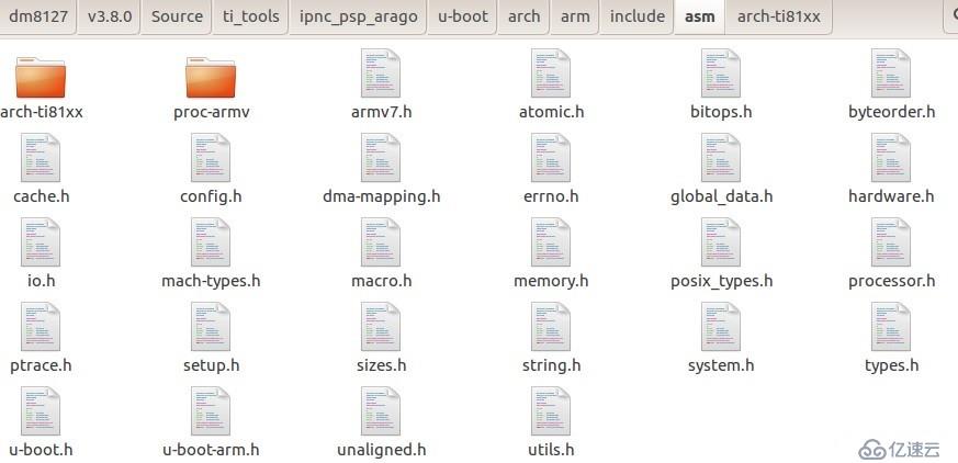
2、回到u-boot目录下,把nand_spl和onenand_ipl文件夹去掉。
3、Include/configs/只保留ti8148_ipnc.h,其他全部删除。
4、arch只保留arm文件
而arm/cpu文件里面只保留arm_cortexa8
arm_cortexa8文件里只保留
arch/arm/ Include/asm裁剪截图见下图:
5、board文件夹只保留提ti文件夹,ti下面只保留ti8148_ipnc
经过上面几个步骤的暴力删除,DM8127平台的UBOOT简洁了很多,保存备份很方便。
6、u-boot/include/configs/ti8148_ipnc.h重点修改
对于新手玩一个DEMO板来说,要把板子跑起程序来,其实移植工作很大一部分在这个文件下去修改,其他外设驱动初始化,则还没有那么着急。等你弄熟DEMO板,然后再去开发自己设计的板子,比如使用新的DDR3啊,NAND FLASH啊,网口芯片啊等等。
下面本人直接把本公司的开发板u-boot源码对于的/include/configs/ti8148_ipnc.h放上来逐步分析。
#ifndef __CONFIG_TI8148_IPNC_H
#define __CONFIG_TI8148_IPNC_H
/
#define CONFIG_TI814X_NO_RUNTIME_PG_DETECT
/
/ Display CPU info /
#define CONFIG_DISPLAY_CPUINFO 1 (允许串口打印CPU信息)
/ In the 1st stage we have just 110K, so cut down wherever possible */
#ifdef CONFIG_TI814X_MIN_CONFIG (使用make ubootmin,就编译这里面的定义)
/ enable d-cache only on 2nd stage /
#define CONFIG_SYS_DCACHE_OFF
#define CONFIG_CMD_MEMORY / for mtest /
#define CONFIG_CMD_MISC / Misc functions like sleep etc/(支持sleep 1这种脚本命令)
#undef CONFIG_GZIP (ubootmin不需要过多的其他功能,使用#undef处理)
#undef CONFIG_ZLIB
#undef CONFIG_SYS_HUSH_PARSER
#define CONFIG_CMD_LOADB / loadb /
#define CONFIG_CMD_LOADY / loady /
#define CONFIG_SETUP_PLL
#define CONFIG_TI814X_CONFIG_DDR(在ubootmin里面必须对DDR3进行初始化,否则无法运行uboot)
#define CONFIG_TI814X_EVM_DDR3
#define CONFIG_ENV_SIZE 0x400 (ubootmin也有自己的boot 参数,字节很少)
#define CONFIG_SYS_MALLOC_LEN (CONFIG_ENV_SIZE + (8 * 1024))
#define CONFIG_SYS_PROMPT "TI-MIN#" (ubootmin命令行,不过一般只用于开发调试)*
/ set to negative value for no autoboot /
#define CONFIG_BOOTDELAY 0 (ubootmin在开发调试可以为1,ubootmin稳定后产品化为0)
#if defined(CONFIG_SPI_BOOT) / Autoload the 2nd stage from SPI /
#error 1 (ubootmin不需要SPI BOOT的话,这里面不编译)
#define CONFIG_SPI 1
#if defined(CONFIG_TI81XX_PCIE_BOOT)
#define CONFIG_CMDLINE_TAG 1 / enable passing of ATAGs /
#define CONFIG_SETUP_MEMORY_TAGS 1
#define CONFIG_INITRD_TAG 1 / Required for ramdisk support /
#define CONFIG_CMD_SOURCE
#define CONFIG_EXTRA_ENV_SETTINGS \
"verify=yes\0" \
"bootcmd=source 0x80400000\0" \
""
/ user can override default size configuration here.
#else //(CONFIG_TI81XX_PCIE_BOOT) (ubootmin不需要PCIE BOOT的话,这里面不编译)
#define CONFIG_EXTRA_ENV_SETTINGS \
"verify=yes\0" \
"bootcmd=sf probe 0; sf read 0x81000000 0x20000 0x40000; go 0x81000000\0" \
#endif //(CONFIG_TI81XX_PCIE_BOOT)
#elif defined(CONFIG_NAND_BOOT) / Autoload the 2nd stage from NAND /
//#error 2 //built: build_1_uboot-min-nand.sh sleep 1 (ubootmin需要NAND BOOT,一定 要编译)
#define CONFIG_NAND 1
#define CONFIG_EXTRA_ENV_SETTINGS \
"verify=yes\0" \
"bootcmd=mw.b 0x81000000 0x00 0x20000;nand read 0x81000000 0x20000 0x40000;go 0x81000000\0" \
(ubootmin存放在0x0—0x20000空间,uboot存放在0x20000---0x180000,这里ubootmin把uboot给跑起来,读取NAND FLASH的UBOOT放到DDR3地址0x81000000,然后go命令BOOT起来)
#elif defined(CONFIG_SD_BOOT) / Autoload the 2nd stage from SD /
//#error 3 //built: build_1_uboot-min-sd (ubootmin需要SD BOOT的话,调试模式和生产模式,要编译)
#define CONFIG_MMC 1
#define CONFIG_EXTRA_ENV_SETTINGS \
"verify=yes\0" \
"bootcmd=mmc rescan 0; fatload mmc 0 0x80800000 u-boot.bin; go 0x80800000\0" \
(ubootmin从SD卡读读u-boot.bin,然后跑起来)
#elif defined(CONFIG_UART_BOOT) / stop in the min prompt /
#define CONFIG_EXTRA_ENV_SETTINGS \
"verify=yes\0" \
"bootcmd=\0" \
#elif defined(CONFIG_ETH_BOOT) / Auto load 2nd stage from server /
#define CONFIG_EXTRA_ENV_SETTINGS \
"verify=yes\0" \
"bootcmd=setenv autoload no;dhcp; tftp 0x81000000 u-boot.bin; go 0x81000000\0"
#endif //defined(CONFIG_SPI_BOOT)
#elif defined(CONFIG_TI814X_OPTI_CONFIG) / Optimized code / (对应本文前面的介绍OPTI串口下载模式,需要这种编译宏,对应make ubootopti)
#include <config_cmd_default.h> (这个.h里面的一些宏定义也可以进去屏蔽掉)
#define CONFIG_ZERO_BOOTDELAY_CHECK
#define CONFIG_ENV_SIZE 0x2000
#define CONFIG_SYS_MALLOC_LEN (CONFIG_ENV_SIZE + (32 1024))
#define CONFIG_ENV_OVERWRITE
#define CONFIG_SYS_LONGHELP
#define CONFIG_SYS_PROMPT "TI8127_OPTI#"
#define CONFIG_CMDLINE_TAG 1 / enable passing of ATAGs /
#define CONFIG_SETUP_MEMORY_TAGS 1
#define CONFIG_INITRD_TAG 1 / Required for ramdisk support /
#define CONFIG_BOOTDELAY 3 / set to negative value for no autoboot */
#define CONFIG_NAND 1
#define CONFIG_SETUP_PLL
#define CONFIG_TI814X_CONFIG_DDR
#define CONFIG_TI814X_EVM_DDR3
#define CONFIG_SYS_DCACHE_OFF
#define CONFIG_SYS_ICACHE_OFF
#define CONFIG_CMD_BDI / bdinfo /
#define CONFIG_CMD_BOOTD / bootd /
#define CONFIG_CMD_CONSOLE / coninfo /
#define CONFIG_CMD_ECHO / echo arguments /
#define CONFIG_CMD_EDITENV / editenv /
#define CONFIG_CMD_FPGA / FPGA configuration Support /
#define CONFIG_CMD_IMI / iminfo /
#define CONFIG_CMD_ITEST / Integer (and string) test /
#ifndef CONFIG_SYS_NO_FLASH
#define CONFIG_CMD_FLASH / flinfo, erase, protect /
#define CONFIG_CMD_IMLS / List all found images /
#endif
#define CONFIG_CMD_LOADB / loadb /
#define CONFIG_CMD_LOADS / loads /
#define CONFIG_CMD_MEMORY / md mm nm mw cp cmp crc base loop mtest /
#define CONFIG_CMD_MISC / Misc functions like sleep etc/
#define CONFIG_CMD_NET / bootp, tftpboot, rarpboot /
#define CONFIG_CMD_NFS / NFS support /
#define CONFIG_CMD_RUN / run command in env variable /
#define CONFIG_CMD_SAVEENV / saveenv /
#define CONFIG_CMD_SETGETDCR / DCR support on 4xx /
#define CONFIG_CMD_SOURCE / "source" command support /
#define CONFIG_CMD_XIMG / Load part of Multi Image /
#undef CONFIG_CMD_BDI
#undef CONFIG_GZIP
#undef CONFIG_ZLIB
#undef CONFIG_CMD_LOADB
#undef CONFIG_CMD_LOADS
#undef CONFIG_CMD_NFS
#undef CONFIG_CMD_SETGETDCR
#undef CONFIG_CMD_XIMG
#undef CONFIG_CMD_MISC
#undef CONFIG_CMD_ITEST
#undef CONFIG_CMD_FPGA
#undef CONFIG_CMD_EDITENV
#undef CONFIG_BOOTM_NETBSD
#undef CONFIG_BOOTM_RTEMS
#undef CONFIG_CMD_MISC
#undef CONFIG_CMD_IMI
#undef CONFIG_CMD_ITEST
#undef CONFIG_CMD_SOURCE
#undef CONFIG_CMD_IMLS
#undef CONFIG_CMD_ECHO
(其实上面有些代码是多余的,因为后面的#undef 是把前面定义的宏给取消了,本人这里是不想破坏TI RDK的架构,让大家明白这个过程。由于OPTI模式编译的BIN也是在内部RAM运行,必须裁剪不需要的UBOOT功能,只保留TFTP网络烧写NAND FLASH的功能就OK了)
#define CONFIG_EXTRA_ENV_SETTINGS \
"verify=no\0" \
"bootdelay=0\0" \
"bootfile=uImage\0" \
"loadaddr=0x81000000\0" \
"bootargs=console=ttyO0,115200n8 mem=256M notifyk.vpssm3_sva=0xBF900000 vram=50M ubi.mtd=4 root=ubi0:rootfs rootfstype=ubifs rw rootwait=1 rw lpj=4997120 ip=${ipaddr}:${serverip}:${gateway}:${subnet}::eth0:off\0 "\
"eraseall=nand erase\0" \
"uboot_tftp=tftp 0x81000000 dm8127_uboot.bin; go 0x81000000 \0" \
#define CONFIG_BOOTCOMMAND \
"nboot 80007FC0 0 0x280000;bootm 80007FC0"
(本人这里只使用网络TFTP下载运行UBOOT,烧写的任务交给这个新运行起来的dm8127_uboot.bin,而不是使用这个OPTI模式的UBOOT)
#else //CONFIG_TI814X_MIN_CONFIG (下面这些定义就是编译正常UBOOT的宏了,很多工作在下面做)
#include <config_cmd_default.h>
#define CONFIG_SERIAL_TAG 1
#define CONFIG_REVISION_TAG 1
#define CONFIG_SKIP_LOWLEVEL_INIT / 1st stage would have done the basic init /
#define CONFIG_ENV_SIZE 0x20000 (用一个BLOCK保存UBOOT参数:bootargs)
#define CONFIG_SYS_MALLOC_LEN (CONFIG_ENV_SIZE + (32 1024))
#define CONFIG_ENV_OVERWRITE
#define CONFIG_SYS_LONGHELP
#define CONFIG_SYS_PROMPT "TI8127_IPNC#"
#define CONFIG_SYS_HUSH_PARSER / Use HUSH parser to allow command parsing /
#define CONFIG_SYS_PROMPT_HUSH_PS2 "> "
#define CONFIG_CMDLINE_TAG 1 / enable passing of ATAGs /(支持从UBOOT传参数给内核)
#define CONFIG_SETUP_MEMORY_TAGS 1
#define CONFIG_INITRD_TAG 1 / Required for ramdisk support /
#define CONFIG_BOOTDELAY 1 / set to negative value for no autoboot /
#define CONFIG_CMD_AUTOTEST / for autotest /
/ By default, 2nd stage will have MMC, NAND, SPI and I2C support */
#define CONFIG_MMC 1
#define CONFIG_NAND 1
#define CONFIG_SPI 1
#define CONFIG_I2C 1
#define CONFIG_EXTRA_ENV_SETTINGS \
"verify=yes\0" \
"bootfile=uImage\0" \
"ramdisk_file=ramdisk.gz\0" \
"loadaddr=0x81000000\0" \
"script_addr=0x80900000\0" \
"loadbootscript=fatload mmc 0 ${script_addr} boot.scr\0" \
"bootscript= echo Running bootscript from MMC/SD to set the ENV...; " \
"source ${script_addr}\0" \
"ubifsargs=setenv bootargs console=ttyO0,115200n8 mem=80M notifyk.vpssm3_sva=0xBFD00000 vram=4M " \
"cmemk.phys_start=0x85000000 cmemk.phys_end=0x89000000 cmemk.allowOverlap=1 earlyprintk " \
"ip=${ipaddr} " \
"rootfstype=ubifs root=ubi0:rootfs init=/init ubi.mtd=5,2048 " \
"rootwait=1 rw lpj=4997120\0" \
"nfsargs=setenv bootargs console=ttyO0,115200n8 mem=80M notifyk.vpssm3_sva=0xBFD00000 vram=4M cmemk.phys_start=0x85000000 cmemk.phys_end=0x89000000 cmemk.allowOverlap=1 earlyprintk lpj=4997120 " \
"ip=${ipaddr} " \
"root=/dev/nfs rw nfsroot=${serverip}:/home/davinci/dm8127/v3.8.0/Source/ipnc_rdk/target/filesys,nolock\0" \
"squashfsargs=setenv bootargs console=ttyO0,115200n8 mem=80M notifyk.vpssm3_sva=0xBFD00000 vram=4M cmemk.phys_start=0x85000000 cmemk.phys_end=0x89000000 cmemk.allowOverlap=1 earlyprintk lpj=4997120 " \
"ip=${ipaddr} " \
"noinitrd rootfstype=squashfs root=/dev/mtdblock4\0" \
"eraseall=nand erase\0" \
"erase_env=nand erase 180000 40000\0" \
"tftp_boot=ipnc_ff_init 1;tftpboot 0x81000000 dm8127_kernel.bin;bootm\0" \
"nfsboot=ipnc_ff_init 1;run nfsargs;nand read ${loadaddr} 1C0000 400000;bootm ${loadaddr}\0" \
"userboot=ipnc_ff_init 1;nand read ${loadaddr} 1C0000 400000;bootm ${loadaddr}\0" \
"squashfsboot=run squashfsargs;ipnc_ff_init 1;nand read ${loadaddr} 1C0000 400000; bootm ${loadaddr}\0" \
"ubifsboot=ipnc_ff_init 1;run ubifsargs;nand read ${loadaddr} 1C0000 400000;bootm ${loadaddr}\0" \
"uboot_tftp=ipnc_ff_init 1;tftp 0x81000000 dm8127_uboot.bin; go 0x81000000\0" \
"updatemin=mw.b 0x81000000 0xFF 0x20000;tftp 0x81000000 dm8127_min.bin;nand erase 0x0 0x20000;nand write.i 0x81000000 0x0 20000\0" \
"updateuboot=mw.b 0x81000000 0xFF 0x40000;tftp 0x81000000 dm8127_uboot.bin;nand erase 20000 160000;nand write.i 0x81000000 20000 ${filesize}\0" \
"updatekernel=tftp 0x81000000 dm8127_kernel.bin;nand erase 1C0000 640000;nand write.i 0x81000000 1C0000 ${filesize}\0" \
"updatebasefs=tftp 0x81000000 dm8127_basefs.bin;nand erase 800000 2300000;nand write.i 0x81000000 800000 ${filesize}\0" \
"updateubifs=tftp 0x81000000 dm8127_ubifs.bin;nand erase 2B00000 6E00000;nand write.i 0x81000000 2B00000 ${filesize}\0" \
""
#define CONFIG_BOOTCOMMAND "run squashfsboot" /or run ubifsboot /
(这里定义上电UBOOT使用run ubifsboot或者 run nfsboot或者run userboot,可以在命令行使用:
Setenv bootcmd ‘run userboot’;saveenv去选择默认上电启动文件系统模式)
#define CONFIG_BOOTARGS \
"console=ttyO0,115200n8 mem=80M notifyk.vpssm3_sva=0xBF900000 vram=4M ubi.mtd=5 root=ubi0:rootfs rootfstype=ubifs rw rootwait=1 lpj=4997120 ip=${ipaddr}\0 "\
#endif
(
上面的有UBOOT 参数适合DDR3 为512M字节系统,我们为了方便NFS调试,定义了nfsargs,如果主文件系统使用squashfs文件系统,我们就使用squashfsargs。如果主文件系统使用ubifs,我们就使用ubifsargs。如果自己设置新的参数,可以setenv bootargs XXXXXXXX,然后使用上面的run userboot。
本公司DM8127开发板NAND FLASH分区信息:
0x000000000000-0x000000020000 : "U-Boot-min"
0x000000020000-0x000000180000 : "U-Boot"
0x000000180000-0x0000001c0000 : "U-Boot Env"
0x0000001c0000-0x000000800000 : "Kernel"
0x000000800000-0x000002b00000 : "Squash"
0x000002b00000-0x000009900000 : "ubifs"
0x000009900000-0x00000e900000 : "userapp"
0x00000e900000-0x000020000000 : "user data"
根据这个信息,我们再看看前面的run updatemin ; run updateuboot; run updatekernel;run updateubifs;
这些命令脚本是本公司自己写的,
run updatemin 通过TFTPSERVER 下载dm8127_min.bin并烧写到NAND FLASH;
run updateuboot下载dm8127_uboot.bin烧写到NAND;
run updatekernel下载dm8127_kernel.bin烧写到NAND;
run updateubifs下载dm8127_ubifs.bin烧写到NAND。
上面有些参数就是cmem共享内存的定义,参考APPRO的定义就可以了,我们DM8127使用全速模式,不是低功耗模式,也不是内存DDR3只有256M那种。
)
#define CONFIG_IPADDR 192.168.1.188 (我们这里定义开发环境的ipaddr)
#define CONFIG_SERVERIP 192.168.1.252 (我们这里定义开发环境的serverip,比如tftp,NFS的主机IP)
#define CONFIG_GATEWAYIP 192.168.1.1
#define CONFIG_NETMASK 255.255.255.0
#define CONFIG_ETHADDR 00:11:22:33:44:55
(我们这里定义板子的MAC地址,后面会在bootm.c添加代码传给kernel,见:
Arch/arm/lib/Bootm.c
在do_bootm_linux()加入:
#if 1 //added by jingbo
char buf1 = malloc(1024);
char buf2 = malloc(32);
sprintf(buf2, "eth=%s", getenv ("ethaddr"));
sprintf(buf1, "%s %s", getenv ("bootargs"), buf2);
setup_commandline_tag (bd, buf1);
#endif
这段代码就是如何把MAC地址通过bootargs传给内核)
#ifndef CONFIG_TI814X_OPTI_CONFIG
#define CONFIG_AUTO_COMPLETE (UBOOT命令补全功能一定要打开,否则在uboot命令行无法使用tab键补全命令)
#define CONFIG_CMDLINE_EDITING(这个支持UBOOT命令行光标键查询历史命令,一般和CONFIG_AUTO_COMPLETE结合使用,一定要加上)
#endif
#define CONFIG_SYS_GBL_DATA_SIZE 128 / size in bytes reserved for
initial data /
#define CONFIG_MISC_INIT_R 1
#ifndef CONFIG_TI814X_MIN_CONFIG
#define CONFIG_TI814X_ASCIIART 1 / The centaur /
#endif
#define CONFIG_SYS_AUTOLOAD "yes"
#ifndef CONFIG_TI814X_OPTI_CONFIG
#define CONFIG_CMD_CACHE
#define CONFIG_CMD_ECHO
#endif
/*
/ max number of command args /
#define CONFIG_SYS_MAXARGS 32
/ Console I/O Buffer Size /
#define CONFIG_SYS_CBSIZE 512
/ Print Buffer Size /
#define CONFIG_SYS_PBSIZE (CONFIG_SYS_CBSIZE \
/ Hardware related /
/**
/**
/*
#define CONFIG_BAUDRATE 115200
#define CONFIG_SYS_BAUDRATE_TABLE { 110, 300, 600, 1200, 2400, \
4800, 9600, 14400, 19200, 28800, 38400, 56000, 57600, 115200 }
/*
#if defined(CONFIG_NO_ETH)
#undef CONFIG_CMD_NET
#else
#define CONFIG_CMD_NET
#define CONFIG_CMD_DHCP
#define CONFIG_CMD_PING
#endif
#if defined(CONFIG_CMD_NET)
#define CONFIG_DRIVER_TI_CPSW
#define CONFIG_MII
#define CONFIG_BOOTP_DEFAULT
#define CONFIG_BOOTP_DNS
#define CONFIG_BOOTP_DNS2
#define CONFIG_BOOTP_SEND_HOSTNAME
#define CONFIG_BOOTP_GATEWAY
#define CONFIG_BOOTP_SUBNETMASK
#define CONFIG_NET_RETRY_COUNT 10
#define CONFIG_NET_MULTI
#define CONFIG_PHY_GIGE
/ increase network receive packet buffer count for reliable TFTP /
#define CONFIG_SYS_RX_ETH_BUFFER 16
#endif
#if defined(CONFIG_SYS_NO_FLASH)
#define CONFIG_ENV_IS_NOWHERE
#endif
/ NAND support /
#ifdef CONFIG_NAND
#define CONFIG_CMD_NAND
#define CONFIG_NAND_TI81XX
//#define GPMC_NAND_ECC_LP_x16_LAYOUT 1 //Jingbo: for 16BIT NAND
#define GPMC_NAND_ECC_LP_x8_LAYOUT 1 //Jingbo: for 8bit NAND
#define NAND_BASE (0x08000000) (NAND FLASH芯片的片选地址 )
#define CONFIG_SYS_NAND_ADDR NAND_BASE / physical address /
/ to access nand /
#define CONFIG_SYS_NAND_BASE NAND_BASE / physical address /
/ to access nand at /
/ CS0 /
#define CONFIG_SYS_MAX_NAND_DEVICE 1 / Max number of NAND /
#endif / devices /
/ ENV in NAND /
#if defined(CONFIG_NAND_ENV)
#undef CONFIG_ENV_IS_NOWHERE
#define CONFIG_ENV_IS_IN_NAND 1
#ifdef CONFIG_ENV_IS_IN_NAND
#define CONFIG_SYS_MAX_FLASH_SECT 520 / max number of sectors in a chip /
#define CONFIG_SYS_MAX_FLASH_BANKS 2 / max number of flash banks /
#define CONFIG_SYS_MONITOR_LEN (256 << 10) / Reserve 2 sectors /
#define CONFIG_SYS_FLASH_BASE boot_flash_base
#define CONFIG_SYS_MONITOR_BASE CONFIG_SYS_FLASH_BASE
#define MNAND_ENV_OFFSET 0x180000 / environment starts here /(这里我们定义uboot bootarg参数保存的起始地址)
#define CONFIG_SYS_ENV_SECT_SIZE boot_flash_sec
#define CONFIG_ENV_OFFSET boot_flash_off
#define CONFIG_ENV_ADDR MNAND_ENV_OFFSET
#endif
#ifndef ASSEMBLY
extern unsigned int boot_flash_base;
extern volatile unsigned int boot_flash_env_addr;
extern unsigned int boot_flash_off;
extern unsigned int boot_flash_sec;
extern unsigned int boot_flash_type;
#endif
#endif / NAND support /
#ifndef CONFIG_TI814X_OPTI_CONFIG
/ SPI support /
#ifdef CONFIG_SPI (如果使用SPI接口的FLASH,这个宏一定要编译,我们公司板子没用SPI FLASH)
#define CONFIG_OMAP3_SPI
#define CONFIG_MTD_DEVICE
#define CONFIG_SPI_FLASH
#define CONFIG_SPI_FLASH_WINBOND
#define CONFIG_CMD_SF
#define CONFIG_SF_DEFAULT_SPEED (75000000)
#define CONFIG_CODEC_AIC26 1
#endif
/ ENV in SPI /
#if defined(CONFIG_SPI_ENV)
#undef CONFIG_ENV_SIZE
#undef CONFIG_ENV_IS_NOWHERE
#define CONFIG_ENV_IS_IN_SPI_FLASH 1
#ifdef CONFIG_ENV_IS_IN_SPI_FLASH
#define CONFIG_ENV_SIZE 0x2000 /use a small env /
#define CONFIG_SYS_FLASH_BASE (0)
#define SPI_FLASH_ERASE_SIZE (4 1024) / sector size of SPI flash /
#define CONFIG_SYS_ENV_SECT_SIZE (2 SPI_FLASH_ERASE_SIZE) / env size /
#define CONFIG_ENV_SECT_SIZE (CONFIG_SYS_ENV_SECT_SIZE)
#define CONFIG_ENV_OFFSET (96 SPI_FLASH_ERASE_SIZE)
#define CONFIG_ENV_ADDR (CONFIG_ENV_OFFSET)
#define CONFIG_SYS_MAX_FLASH_SECT (1024) / no of sectors in SPI flash /
#define CONFIG_SYS_MAX_FLASH_BANKS (1)
#endif
#endif / SPI support */
/ ENV in MMC /
#if defined(CONFIG_MMC_ENV)
#undef CONFIG_ENV_IS_NOWHERE
#define CONFIG_ENV_IS_IN_MMC 1
#define CONFIG_SYS_MMC_ENV_DEV 0
#undef CONFIG_ENV_SIZE
#undef CONFIG_ENV_OFFSET
#define CONFIG_ENV_OFFSET (722931024)
#define CONFIG_ENV_SIZE (8 1024)
#endif / MMC support /
/ NOR support / (NOR FLASH芯片的支持,我们公司基本不用NOR FLASH了)
#if defined(CONFIG_NOR)
#undef CONFIG_CMD_NAND / Remove NAND support /
#undef CONFIG_NAND_TI81XX
#undef CONFIG_SKIP_LOWLEVEL_INIT
#define CONFIG_TI814X_CONFIG_DDR
#define CONFIG_SETUP_PLL
#define CONFIG_TI814X_EVM_DDR3
#undef CONFIG_ENV_IS_NOWHERE
#ifdef CONFIG_SYS_MALLOC_LEN
#undef CONFIG_SYS_MALLOC_LEN
#endif
#define CONFIG_SYS_FLASH_USE_BUFFER_WRITE 1
#define CONFIG_SYS_MALLOC_LEN (0x100000)
#define CONFIG_SYS_FLASH_CFI
#define CONFIG_FLASH_CFI_DRIVER
#define CONFIG_FLASH_CFI_MTD
#define CONFIG_SYS_MAX_FLASH_SECT 512
#define CONFIG_SYS_MAX_FLASH_BANKS 1
#define CONFIG_SYS_FLASH_BASE (0x08000000)
#define CONFIG_SYS_MONITOR_BASE CONFIG_SYS_FLASH_BASE
#define CONFIG_ENV_IS_IN_FLASH 1
#define NOR_SECT_SIZE (128 1024)
#define CONFIG_SYS_ENV_SECT_SIZE (NOR_SECT_SIZE)
#define CONFIG_ENV_SECT_SIZE (NOR_SECT_SIZE)
#define CONFIG_ENV_OFFSET (2 NOR_SECT_SIZE)
#define CONFIG_ENV_ADDR (CONFIG_SYS_FLASH_BASE + CONFIG_ENV_OFFSET)
#define CONFIG_MTD_DEVICE
#endif / NOR support /
/ No I2C support in 1st stage /
#ifdef CONFIG_I2C
#define CONFIG_CMD_I2C
#define CONFIG_CMD_DATE
#define CONFIG_I2C_MULTI_BUS (注意:DM8127支持I2C0,I2C1,I2C2几个I2C总线)
#define CONFIG_SYS_RTC_BUS_NUM 0
#define CONFIG_TPS65911_I2C 1
#define CONFIG_RTC_TPS65911 1 (比如这里电源管理芯片 使用I2C0总线)
#define CONFIG_CODEC_AIC3104 1
#define CONFIG_SENSOR_MT9J003 1
#define CONFIG_HARD_I2C 1
#define CONFIG_SYS_I2C_SPEED 100000 (I2C总线使用100K速率)
#define CONFIG_SYS_I2C_SLAVE 1
#define CONFIG_SYS_I2C_BUS 0
#define CONFIG_SYS_I2C_BUS_SELECT 1
#define CONFIG_DRIVER_TI81XX_I2C 1
/ EEPROM definitions /
#define CONFIG_SYS_I2C_EEPROM_ADDR_LEN 3
#define CONFIG_SYS_I2C_EEPROM_ADDR 0x50
#define CONFIG_SYS_EEPROM_PAGE_WRITE_BITS 6
#define CONFIG_SYS_EEPROM_PAGE_WRITE_DELAY_MS 20
#endif
/ HSMMC support / (HSMMC这里我们没有用到)
#ifdef CONFIG_MMC
#define CONFIG_CMD_MMC 1
#define CONFIG_GENERIC_MMC
#define CONFIG_OMAP_HSMMC
#define CONFIG_DOS_PARTITION 1
#define CONFIG_CMD_FAT 1
#endif
#endif / CONFIG_TI814X_OPTI_CONFIG /
/ U-boot Version /
#define CONFIG_VERSION_VARIABLE
#ifdef CONFIG_TI814X_MIN_CONFIG
#define CONFIG_IDENT_STRING " DM8127_IPNC_3.80.00 min"
#else
#define CONFIG_IDENT_STRING " DM8127_IPNC_3.80.00"
#endif
/ Unsupported features /
#undef CONFIG_USE_IRQ
#endif / ! __CONFIG_TI8148_IPNC_H /
好了,u-boot/include/configs/ti8148_ipnc.h这个最重要的平台信息汇总文件修改告一段落。
7、u-boot/arch/arm/lib/board.c和u-boot/board/ti/ti8148_ipnc/evm.c的修改
无论是ubootmin还是uboot,所有的DDR3初始化,NAND初始化,PLL初始化,外设芯片初始化,GPIO管脚复用设置,都在这两个文件去修改。当然修改之前,一定要先了解DM8127的管脚复用,如果嵌入式软件工程师特别是驱动工程师不了解这个管脚复用,根本就玩不转DM8127。我们先看源码:
u-boot/board/ti/ti8148_ipnc/mux.h
还要就是要看DM8127 芯片DATASHEET第153页开始的表格(PINCNTLx Registers MUXMODE Functions),同时结合DM8127用户手册sprugz8g.pdf去分析DM8127功能模块的复用情况。
这里本人举个例子:
/ 256-UART5_RXD 227-UART5_TXD /
/ldz_add (228)GP3_20:rs485_2_en/
/ -228 / BIT(0), BIT(5), BIT(5), BIT(7),
这里是复用寄存器表从225到228对应的地址偏移,上面我们要把GP3_20设置成GPIO模式,使能UART5,那么UART5对应PINCNTLx Registers MUXMODE Functions的管脚和对应的寄存器偏移地址是226和227,BIT(5)表示使用UART5,里面的(5)标示第5种模式就是使用UART5,GP3_20要配置成GPIO模式必须设置228寄存器偏移地址为BIT(7),里面的(7)表示GPIO模式。 (0)表示默认disable模式或者TI对应管脚默认模式。
上面提到的DM8127功能模块初始化,我们需要看看board.c的sequence[]里面的初始化函数和evm.c的board_init()函数。可以从这两个文件去修改添加一些初始化,GPIO默认状态初始化等等,看源代码就清楚了,这里不累赘。
DM8127的UBOOT裁剪和简单移植上面基本介绍结束,本人这里是介绍比较简单,因为人家TI 第3方APPRO RDK软件包做得很好了,比如在UBOOT测试一些外设硬件,可以看看common\ cmd_autotest.c,非常有用,当然你要在UBOOT添加很多功能,可以自己在这个RDK的UBOOT软件包的基础上深入去设计。有关DM8127开发攻略基本写得差不多了,本人总发现时间不够用,公司除了开发完DM8127各种客户定义功能,还得忙开发廉价平台海思平台Hi3516A/D,这个廉价平台1080P方案也基本开发结束。公司现在全力开发支持深度学习算法得一个新的嵌入式平台,国内某个独角兽公司已经推出类似产品了,还有其他大公司也开发出产品了,我们也不能落后太多,到时候再公布,为一些有好算法的公司提供可靠嵌入式平台。本人这里再次强调一下,DM8127适合传统机器视觉算法运行,运行不了深度学习算法。在很多图像分析方面,不一定要使用深度学习算法。还有, TI 的浮点DSP非常适合不同功能的C/C++算法移植,海思平台的算法是固化到芯片,只能做某方面的图像处理,而FPGA对很多只专长C/C++算法的而欠缺硬件知识来说,开发FPGA是一件很痛苦的事情,现在产品生命周期很短,抓紧时间抢占市场才是王道,否则到后期产品打价格战,后来推出没价格优势的平台会输得很惨。
免责声明:本站发布的内容(图片、视频和文字)以原创、转载和分享为主,文章观点不代表本网站立场,如果涉及侵权请联系站长邮箱:is@yisu.com进行举报,并提供相关证据,一经查实,将立刻删除涉嫌侵权内容。