您好,登录后才能下订单哦!
1. 概述
HDMI英文名为High Definition Multimedia Interface,是一种数字化视频、音频接口。 现已
广泛应用于高清数字电视、PC显示器等产品中。
这里我们使用Silicon Image公司的SiI9134作为HDMI发送芯片,支持HDMI 1.3标准。

2. 设计框图
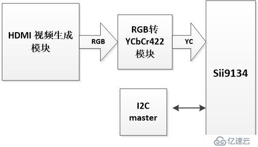
视频源由FPGA内部产生,sii9134的配置通过I2C模块完成。这里以720P60为例完成设计。

3. Sii9134配置
这里将Sii9134配置成YCbCr422输入,RGB444输出模式。
void sii9134_init()
{
    sccb_senddata(0x72,0x05,0x01);	//reset all sections
    sccb_senddata(0x72,0x05,0x00);	//disable reset

    sccb_senddata(0x72,0x08,0x37);	//VSYNC and HSYNC, 24bit, rising edge, normal operation

    sccb_senddata(0x72,0x0c,0x00);
    sccb_senddata(0x72,0x0d,0x01);

    sccb_senddata(0x72,0x4B,0x00);	//Blue
    sccb_senddata(0x72,0x4C,0x00);	//Green
    sccb_senddata(0x72,0x4D,0xff);	//Red

    sccb_senddata(0x72,0x82,0x25);	//FPLL*IDCK, enable internal source termination
    sccb_senddata(0x72,0x83,0x19);	//HDMI PLL/2, PLL filter feedback/4, PLL filter front/2
    sccb_senddata(0x72,0x84,0x31);	//50uA, PLL filter post/2
    sccb_senddata(0x72,0x85,0x01);	//HDMI transmitter PLL front/2

    sccb_senddata(0x72,0x32,0x04);	//h-blank
    sccb_senddata(0x72,0x33,0x41);	//enable DE, positive polarity, left-blank(370 pixels)
    sccb_senddata(0x72,0x34,0x19);	//v-blank(30 lines)
    sccb_senddata(0x72,0x36,0x00);	//the width of active display
    sccb_senddata(0x72,0x37,0x05);	//the width of active display(1280)
    sccb_senddata(0x72,0x38,0xD0);	//the height of active display
    sccb_senddata(0x72,0x39,0x02);	//the height of active display(720)

	sccb_senddata(0x72,0x3E,0x00);
	sccb_senddata(0x72,0x40,0x6e);
	sccb_senddata(0x72,0x41,0x00);
	sccb_senddata(0x72,0x44,0x29);
	sccb_senddata(0x72,0x45,0x00);
	sccb_senddata(0x72,0x46,0x05);
	sccb_senddata(0x72,0x47,0x06);

	sccb_senddata(0x72,0x48,0x30);
	sccb_senddata(0x72,0x49,0x00);
	sccb_senddata(0x72,0x4a,0x3c);

////////////////////////////////////////////////
	sccb_senddata(0x7a,0x01,0x02);
	sccb_senddata(0x7a,0x02,0x01);
	sccb_senddata(0x7a,0x03,0x00);
	sccb_senddata(0x7a,0x04,0x18);
	sccb_senddata(0x7a,0x05,0x00);

	sccb_senddata(0x7a,0x14,0x11);
	sccb_senddata(0x7a,0x1D,0x40);
	sccb_senddata(0x7a,0x21,0x02);
	sccb_senddata(0x7a,0x22,0x2B);

	sccb_senddata(0x7a,0x2F,0x01);

	sccb_senddata(0x7a,0x40,0x82);
	sccb_senddata(0x7a,0x41,0x02);
	sccb_senddata(0x7a,0x42,0x0d);
	sccb_senddata(0x7a,0x43,0x59);
	sccb_senddata(0x7a,0x44,0x11);
	sccb_senddata(0x7a,0x45,0x28);
	sccb_senddata(0x7a,0x46,0x00);
	sccb_senddata(0x7a,0x47,0x04);
	sccb_senddata(0x7a,0x48,0x00);
	sccb_senddata(0x7a,0x49,0x00);
	sccb_senddata(0x7a,0x4A,0x00);
	sccb_senddata(0x7a,0x4B,0xD1);
	sccb_senddata(0x7a,0x4C,0x02);
	sccb_senddata(0x7a,0x4D,0x00);
	sccb_senddata(0x7a,0x4E,0x00);
	sccb_senddata(0x7a,0x4F,0x01);
	sccb_senddata(0x7a,0x50,0x05);
	sccb_senddata(0x7a,0x51,0x00);
	sccb_senddata(0x7a,0x52,0x00);

	sccb_senddata(0x7a,0x80,0x84);
	sccb_senddata(0x7a,0x81,0x01);
	sccb_senddata(0x7a,0x82,0x0a);
	sccb_senddata(0x7a,0x83,0x70);
	sccb_senddata(0x7a,0x84,0x01);
	sccb_senddata(0x7a,0x85,0x00);
	sccb_senddata(0x7a,0x86,0x00);
	sccb_senddata(0x7a,0x87,0x00);
	sccb_senddata(0x7a,0x88,0x00);
	sccb_senddata(0x7a,0x89,0x00);
	sccb_senddata(0x7a,0x8a,0x00);
	sccb_senddata(0x7a,0x8b,0x00);
	sccb_senddata(0x7a,0x8c,0x00);
	sccb_senddata(0x7a,0x8d,0x00);
	sccb_senddata(0x7a,0x3e,0x33);
}
4. FPGA逻辑设计
FPGA逻辑完成视频源生成、HDMI配置、RGB转YCbCr功能。下面表格给出RGB转YC的公式。
Video Format | Formulas |
576p | Y = 0.299R′ + 0.587G′ + 0.114B′ |
480p | |
240p | |
720p | Y = 0.213R′ + 0.715G′ + 0.072B′ |
1080p |
//file name:		    hdmi_vid_gen.v
//author:			shugen.yin
//date:				2016.9.21
//function:			hdmi video generation
//log:

module hdmi_vid_gen(
	input clk,  //74.25MHz
	input rst_n,

	output								hdmi_clk,
	output								hdmi_txde,
	output								hdmi_hs,
	output								hdmi_vs,
	output [15:0] 						hdmi_data
);


parameter IMG_HDISP	= 16'd1280;
parameter IMG_VDISP  = 16'd720;
parameter H_OFFSET   = 0;

wire pclk;
assign pclk = clk;

assign hdmi_clk  = pclk;
assign hdmi_hs  = hsync;
assign hdmi_txde = data_valid;
assign hdmi_vs  = vsync;
assign hdmi_data = data;

reg [11:0] vcnt;
reg [15:0] hcnt;
reg vsync;
reg hsync;
reg data_valid;
reg [15:0] data;
reg [7:0] red;
reg [7:0] green;
reg [7:0] blue;


always @(posedge pclk)
	if(hcnt>=(IMG_HDISP+259))		//720p
		hcnt <= 0;
	else
		hcnt <= hcnt + 1'b1;

always @(posedge pclk)
	if(hcnt>=(IMG_HDISP+259))
		if(vcnt>=(IMG_VDISP+24))
			vcnt <= 0;
		else
			vcnt <= vcnt + 1'b1;
	else
		vcnt <= vcnt;


always @(posedge pclk)
	if((hcnt>=IMG_HDISP+H_OFFSET) & (hcnt<=(IMG_HDISP+H_OFFSET+32)) & (vcnt>=0 | (vcnt<IMG_VDISP)))
		hsync <= 1'b1;
	else
		hsync <= 1'b0;

always @(posedge pclk)
	if(vcnt<=(IMG_VDISP+2+6) & vcnt>=(IMG_VDISP+2))
		vsync <= 1'b1;
	else
		vsync <= 1'b0;

reg cbcr_reg;

always @(posedge pclk)
	if(vsync)
	begin
		data <= 0;
		cbcr_reg <= 0;
		red <= 0;
		green <= 0;
		blue <= 0;
	end
	else if((hcnt>=0) & (hcnt<(IMG_HDISP+0)) & (vcnt>=0) & (vcnt<(0+IMG_VDISP/4)))
	begin
		if(~cbcr_reg)
		begin
			data[7:0] <= y;
			data[15:8] <= cb;
		end
		else
		begin
			data[7:0] <= y;
			data[15:8] <= cr;
		end
		cbcr_reg <= ~cbcr_reg;
		red   <= 8'hf0;
		green <= 8'hf0;
		blue  <= 8'h00;
	end
	else if((hcnt>=0) & (hcnt<(IMG_HDISP+0)) & (vcnt>=(0+IMG_VDISP/4)) & (vcnt<(0+2*IMG_VDISP/4)))
	begin
		if(~cbcr_reg)
		begin
			data[7:0] <= y;
			data[15:8] <= cb;
		end
		else
		begin
			data[7:0] <= y;
			data[15:8] <= cr;
		end
		cbcr_reg <= ~cbcr_reg;
		red   <= 8'hf0;
		green <= 8'h00;
		blue  <= 8'h00;
	end
	else if((hcnt>=0) & (hcnt<(IMG_HDISP+0)) & (vcnt>=(0+2*IMG_VDISP/4)) & (vcnt<(0+3*IMG_VDISP/4)))
	begin
		if(~cbcr_reg)
		begin
			data[7:0] <= y;
			data[15:8] <= cb;
		end
		else
		begin
			data[7:0] <= y;
			data[15:8] <= cr;
		end
		cbcr_reg <= ~cbcr_reg;
		red   <= 8'h00;
		green <= 8'hf0;
		blue  <= 8'h00;
	end
	else if((hcnt>=0) & (hcnt<(IMG_HDISP+0)) & (vcnt>=(0+3*IMG_VDISP/4)) & (vcnt<(0+IMG_VDISP)))
	begin
		if(~cbcr_reg)
		begin
			data[7:0] <= y;
			data[15:8] <= cb;
		end
		else
		begin
			data[7:0] <= y;
			data[15:8] <= cr;
		end
		cbcr_reg <= ~cbcr_reg;
		red   <= 8'h00;
		green <= 8'h00;
		blue  <= 8'hf0;
	end
	else
	begin
		data <= 0;
		cbcr_reg <= 0;
		red <= 0;
		green <= 0;
		blue <= 0;
	end


always @(posedge pclk)
	if(vsync)
		data_valid <= 0;
	else if((hcnt>=0) & (hcnt<(IMG_HDISP+0)) & (vcnt>=0) & (vcnt<(0+IMG_VDISP/4)))
		data_valid <= 1;
	else if((hcnt>=0) & (hcnt<(IMG_HDISP+0)) & (vcnt>=(0+IMG_VDISP/4)) & (vcnt<(0+2*IMG_VDISP/4)))
		data_valid <= 1;
	else if((hcnt>=0) & (hcnt<(IMG_HDISP+0)) & (vcnt>=(0+2*IMG_VDISP/4)) & (vcnt<(0+3*IMG_VDISP/4)))
		data_valid <= 1;
	else if((hcnt>=0) & (hcnt<(IMG_HDISP+0)) & (vcnt>=(0+3*IMG_VDISP/4)) & (vcnt<(0+IMG_VDISP)))
		data_valid <= 1;
	else
		data_valid <= 0;


wire [7:0] y;
wire [7:0] cb;
wire [7:0] cr;

rgb2ycbcr rgb2ycbcr_inst
(
	.clk(pclk) ,	// input  clk_sig
	.rst_n(rst_n) ,	// input  rst_n_sig
	.red(red) ,	// input [7:0] red_sig
	.green(green) ,	// input [7:0] green_sig
	.blue(blue) ,	// input [7:0] blue_sig
	.y(y) ,	// output [7:0] y_sig
	.cb(cb) ,	// output [7:0] cb_sig
	.cr(cr) 	// output [7:0] cr_sig
);


endmodule
5. 最终结果
在显示器上显示1280*720@60帧的彩条视频。

免责声明:本站发布的内容(图片、视频和文字)以原创、转载和分享为主,文章观点不代表本网站立场,如果涉及侵权请联系站长邮箱:is@yisu.com进行举报,并提供相关证据,一经查实,将立刻删除涉嫌侵权内容。